TECHNICAL INVESTIGATION

17/2/17
The technical investigation of a roof should cover
-
-its present condition,
-
-its constructional details; or
-
-if it is deteriorated at least an estimate of its original constructional details; and
-
-an explanation of why it has deteriorated or failed.
-
These can be reported as separate sections or as a single narrative as below. For a full understanding the method of recording should be included.
It can also comment on whether the constructional details were inherently unsuitable and recommend changes for repair or renewal.
The report should aim to be a basis for re-slating by identifying features which may need to be altered or which can be retained.
Method
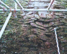
The investigation covered an area of about two metres width from eaves to ridge on both sides of the roof and was carried out from a scaffold at three levels: at the eaves and at approximately 6 and 12m above the eaves. This allowed all areas of the roof to be reached for careful dismantling by hand. The whole area under investigation was covered and weather proofed with scaffold sheeting. To ensure adequate lighting for photography and late working two portable tripod mounted floodlights were used.
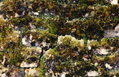
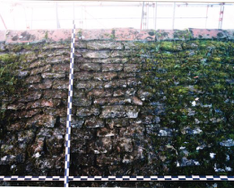
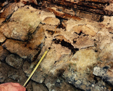
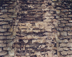
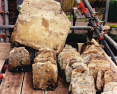
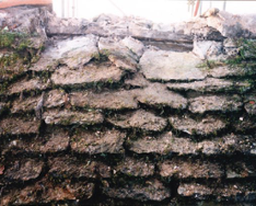
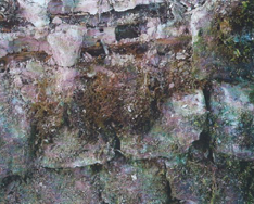
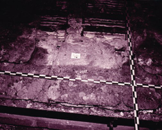
The plant growth was so thick over most of the roof that the vertical and bottom edges of the slates were often obscured (Fig 1). The stone slates were therefore cleaned off with a scraper and stiff hand brush prior to progressive stripping from the ridge. As each course was removed the exposed area below was photographed using 400ASA monochrome and colour negative film. The photographs were taken from a point perpendicular to the slating wherever the scaffold permitted and included scale rules with 50mm divisions (Figs 2 & 3). Groups of slates were also photographed laid out on the scaffold to record their shape, degree of shouldering and the ratio of the length to the width. All these factors are important in preventing the penetration of rain water.
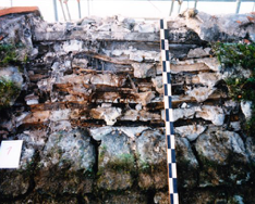
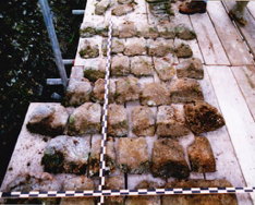
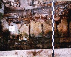
The slate length, head lap and margin - the vertical dimension of the exposed area of the slate - were measured at each course (Fig 4) except where the courses had collapsed onto each other (Fig 10). Where this was the case only the slate length was meaningful. The slate lengths reported here are the distance below the fixing hole.
On a roof of this type and especially because of its deteriorated condition, measurements of head laps and margins cannot be precise. The margins vary considerably along each course. Also, the head lap is somewhat theoretical. It is a dimension by which the roof is set out rather than the actual head lap achieved which is affected by the shape of the slate's top edge and the position of the fixing hole. The head lap achieved depends firstly, on the position of the perpendicular joint in relation to the curve of the slate head (if it drops below the peg hole) and secondly, on the position of the peg hole in relation to the perpendicular joint. For these reasons it is not possible to back calculate any of the three measured dimensions from the other two. References to head laps in this report are the setting out laps unless indicated otherwise.
In spite of these difficulties, with care and a large number of measurements it has been possible to draw conclusions about both the intended construction of the roof and what has been achieved in practice.
Roof condition
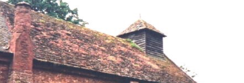
The church stands in a very sheltered environment - it is surround by tall trees on all sides. This will have reduced the extent to which the roof will have been able to dry out between periods of rain.
The investigated roof area is entirely formed of Harnage stone slates, mortar bedded on oak laths and hung with oak pegs except over the rafters where ferrous nails have been used for fixing. The rafter pitch is 50°. The laths varied from about 64 x 10 mm at the eaves to about 30 x 10 mm in the upper courses. The composition of the mortar has not been investigated but it has been proposed that it is probably a 1:1:6 cement:lime:sand mixture. There is no provision for a flow of air through the rafter space consequently any dampness below the roof surface could only escape through the ceiling or the slates.
The stone slates are generally small. Slates 12" long or less account for 82% of the courses on the north slope and 85% of the south. The largest slates are 22" long on the north slope and 26" on the south. In general the slates are not excessively shouldered although there were examples of very poorly shaped slates which would certainly have resulted in water penetration (Figs 7 & 11). There were many instances where slates which, in principle, were not too narrow to be used but which, because of the setting out of the roof, had far too small a side lap (Figs 1 & 11).
The holing of the stone slates is a mixture of mechanically drilled and about 30% hand pecked (Fig 6). This may mean that in 1936 at least 30% were reclaimed from the previous roof. Some of the slates had been reshaped for re-use sometimes involving turning through 90. This does not appear to have weakened them.
At the top of the slopes the slates lie at a pitch of 10 to 18 (Fig 8). This will have increased the amount of water penetration. Elsewhere their pitch was generally about 30. Since the pitch of the slates is dependent on their thickness, length and head lap it is inevitable that it will reduce for the smaller slates towards the top of the roof slopes.
Many of the laths have bowed down-slope leading to reduction of the head laps. At the upper courses where the laths were small - 30 x 10 mm - this is likely to have occurred early in the life of the roof. However most of the bowing has been a consequence of the rotting of the laths.
The slates have been bedded in large quantities of mortar (Figs 4 & 5). Over most of the roof the space between the laths was completely filled with mortar and in places this extends almost to the tail of the course above.
The plants which have established on the roof, especially the ferns on the north slope, have dammed the flow of water down the perpendicular joints increasing the extent of water penetration between the slates (Fig 1). Their presence will have also reduced the speed and extent to which the slates and the rafter space could dry out. The fern roots have spread between the slates lifting them and allowing more water to penetrate and aggravating the drainage problems (Fig 9). All these factors have created and maintained wet conditions at the laths and rafters.
The north slope was wet and substantially deteriorated. Over a large area the laths and pegs were rotted and 11 courses in the middle section were completely collapsed (Fig 10). Consequently the slates here had slid down the slope - reducing the head lap (Fig 11) - and were also resting on the ceiling. In this area it was not possible to measure the constructional details. In the wettest areas the rafters have been slightly affected by rotting and the battens supporting the ceiling have rotted away leading to collapse of the ceiling which has been subsequently repaired. The lowest courses, where the slates and head laps were larger, were in much better condition and generally drier (Fig 12). On the north slope the limit of badly rotted laths coincides approximately with the courses of 12" slates and 3" head laps.
The south slope was in better condition and although the laths and pegs were damp and weakened they have not rotted away as on the north slope. The constructional details - laps, mortaring etc - were essentially the same as those on the north slope and will have resulted in a similar degree of water penetration. This indicates that the south slope has dried out more quickly or thoroughly than the north.
There were less plants on the south slope than on the north and in particular fewer ferns. This will be at least partly due to the drier conditions which would hamper their establishment and growth. In turn their absence would allow faster drying below the slates.
Measured head laps vary between 4" and zero. It appears that the general intention was to set out the roof for a 3" head lap in the lower courses reducing to 2" towards the ridge (It is correct that the head lap should not exceed one third of the slate length.) In the event, neither the minimum nor adequate head laps have been achieved in many instances. It may be that because of the difficulties in obtaining a good supply of stone slates (Annexes 2 & 3) the roofer decided to reduce the head lap to be able to cover the whole roof.
The recorded slate lengths, margins and head laps are tabulated in Annex 1.
Summary of the Reasons for the failure of the roof.
The immediate cause of failure was the rotting of the laths and pegs brought on by the persistent wet conditions below the stone slates. The following factors have contributed to this failure:
-
-Inadequate head laps due to poor setting out of the coursing, bowing of laths and possibly due to insufficient slates to cover the roof area at the appropriate lap.
-
-Inadequate side lap, partly due to poor setting out and/or inadequate supplies of suitably wide slates.
-
-The generally small size of the slates which, because of their curved top edge, further reduces the head and side laps. The smaller the slate the more extreme is the reduction.
-
-Excessive mortaring. In all cases the mortar will have held any moisture creating an environment for wood rot. In the worst cases the mortar was so close to the exposed edges of the slates that it will have drawn moisture into roof.
-
-Plant growth on the roof. This has had the effect of reducing the flow of water down the roof and damming the drainage down the perpendicular joints and increasing the spread of water between the slates and into the lath space.
-
-Plant roots between the slates, especially ferns. These will have had a similar effect to the mortar in creating and maintaining a damp environment. (Plant transpiration must also to some extent result in moisture removal during dry periods.) The fern roots have also forced slates apart increasing the likelihood of water penetration.
-
-Condensation of moisture from the interior of the church within the roof structure. Reportedly there is little or no ventilation out of the body of the church.
-
-Lack of ventilation through the rafter space and through the slating.
-
-The very sheltered environment around the church which will have reduced drying of the roof, especially the north slope, and, consequently, encouraged plant growth.
Suitability of the slates for re-use.
Generally the mortar adhering to the slates can be removed without difficulty or damaging them. A large proportion of the slates were in surprisingly sound condition considering the wet conditions in which they have survived for 60 years (or more in the case of the reused slates). This confirms that Harnage stone slates are very durable and suggests that, because there was a large loss of slates in 1936 that the pre-C20th roof was of great age.
Although a good proportion of the stone slates are sound enough to be reused, if the new roof is to be better able to resist water penetration it would be wise to avoid the use of the smaller, say less than 13 inch, slates except on the highest courses.
Any reused slates should be carefully inspected and dressed to ensure they are free of physical defects and of a suitable shape to provide good side lap.
Reconstruction
Inspection of Harnage roofs at Wilderhope Manor and Langley Chapel indicates that there is nothing inherently unsuitable about Harnage stone slates which would require extreme or special precautions in reconstructing the church roof. Provided the roof pitch is steep - 50 degrees is satisfactory, the head and side laps are adequate and the construction does not promote condensation or moisture retention there is no reason to doubt that the roof will have a very long life..
Therefore the primary technical objectives for the design and reconstruction should be to:
-
-reduce the penetration of water through the stone slating;
-
-reduce as far as possible the amount of moisture from within the church passing into the rafter space and condensing;
-
-adequately ventilate any moisture which does get into the roof structure and
-
-to establish a maintenance programme to ensure these objectives are not compromised subsequently.
The technical specification should also avoid any change to the appearance of the roof and respect the traditional local detailing.
1
2
3
4
5
6
7
8
9
10
11
12